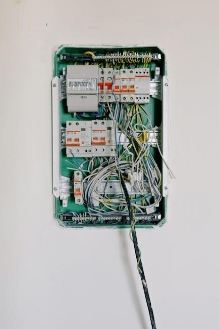
A 2-way switch wiring diagram is a visual guide showing how to connect switches, wires, and components to control lighting from two locations safely and effectively.
What is a 2-Way Switch?
A 2-way switch is an electrical component designed to control a light or appliance from two different locations. It has three terminals: a common (C), L1, and L2. Unlike a standard one-way switch, a 2-way switch operates by creating or breaking the circuit connection between these terminals, allowing you to toggle the load (e.g., a light) on or off from either switch. This setup is commonly used in staircases, hallways, or large rooms where multiple control points are needed. The switch itself doesn’t have an “on” or “off” position; its state depends on the connection configuration. Proper wiring is essential for safe and reliable operation.
Components Involved in a 2-Way Switch Circuit
A 2-way switch circuit typically includes a 2-way switch, terminals (common, L1, L2), live, neutral, and earth wires. The switch connects to the load (e.g., a light) and power source. Wires like the “loop” or “strapper” link switches in multi-control setups. Connectors and cables ensure secure connections. Optional components include intermediate switches or dimmers for enhanced control. Proper wiring ensures safe and efficient operation, avoiding short circuits or power loss. Understanding these components is crucial for interpreting wiring diagrams accurately.
Purpose of a 2-Way Switch Wiring Diagram
A 2-way switch wiring diagram serves as a clear guide to understanding and installing circuits for controlling lights or devices from two locations. It illustrates the connections between switches, wires, and loads, ensuring proper installation. The diagram helps electricians and DIYers visualize how power flows through the circuit. By showing the arrangement of components like terminals (common, L1, L2) and wire colors, it simplifies troubleshooting and ensures safety. Understanding the diagram is essential for maintaining circuit functionality and avoiding potential hazards.

Understanding the Components
Understanding the components involves knowing the three terminals (common, L1, L2) and wiring colors (black, red, earth) for proper installation and safe electric connections.
Two-Way Switch Terminal Explanation
A two-way switch has three terminals: common (COM), L1, and L2. The COM terminal connects to the power source or load, while L1 and L2 act as control points. When the switch is toggled, the circuit between COM and either L1 or L2 changes, enabling control from two locations. Proper identification of these terminals is crucial for correct wiring to ensure the switch functions as intended without short circuits or power loss.
Wiring Colors and Their Functions
In a 2-way switch wiring diagram, wiring colors play a crucial role in identifying connections. The black wire is typically the live (hot) wire, while the red wire serves as the switch leg connecting the switch to the load. The white wire is the neutral, completing the circuit, and the copper wire is the ground, ensuring safety. Understanding these color codes is essential for correct wiring, as they help in identifying the power source, control points, and safety connections, minimizing the risk of electrical hazards and ensuring the circuit operates as intended.
Additional Components (Connectors, Cables)
Beyond the switch itself, connectors and cables are vital in a 2-way wiring setup. Terminal strips or connectors are used to secure wires, ensuring reliable connections. Cables, such as 3-core or 4-core varieties, carry power and control signals between switches and lights. These components are color-coded for clarity, with the 3-core cable typically housing live, neutral, and earth wires. Properly selecting and installing these elements ensures safe and efficient circuit operation, while also simplifying future maintenance or troubleshooting of the 2-way switch system.

How to Read a 2-Way Switch Wiring Diagram
Learn to interpret symbols, trace connections, and understand the flow of electricity in a 2-way switch circuit using a clear, labeled diagram for safe installations.
Identifying Terminals and Wires
In a 2-way switch wiring diagram, identify the terminals as Common (C), L1, and L2. The black wire is the live (hot) wire, while the red wire connects the switches. The copper wire is the ground. Each terminal is labeled, and wires are color-coded for easy identification. Ground wires ensure safety, and their connections are critical. Always refer to the diagram to match wires with the correct terminals. Proper identification ensures safe and functional installations, avoiding short circuits or power loss. Use the correct wire gauges for reliable connections.
Understanding the Circuit Layout
The circuit layout in a 2-way switch wiring diagram illustrates how electricity flows from the power source, through the switches, and to the load. The power source connects to one switch, linking to the second switch, creating a pathway for the current. Both switches are interconnected, allowing control of the load from either location. The live wire from the power source enters the first switch and is then directed to the second switch before reaching the load. Neutral and ground wires complete the circuit, ensuring safe operation. Proper connections are crucial for functionality and safety, preventing short circuits and ensuring reliable control always.
Common Symbols Used in Wiring Diagrams
In wiring diagrams, symbols represent components like switches, lights, and connectors. A two-way switch is often shown as a rectangle with three terminals: Common (C), L1, and L2; Wires are depicted as lines connecting these symbols, with colors indicating their purpose—black for live, blue for neutral, and green/yellow for ground. Arrows or dots denote connections, while loops or parallel lines show live paths. These symbols ensure clarity, making the circuit layout easy to interpret and implement correctly, reducing confusion during installation and troubleshooting processes.

Standard 2-Way Switch Wiring Configuration
A standard 2-way switch wiring configuration connects the power source to one switch, then links both switches via a 3-wire system, ensuring the load is controlled from either location.
Connecting the Power Source
Connecting the power source in a 2-way switch setup involves linking the live wire to the common terminal of the first switch. This ensures the power supply is appropriately routed through the circuit. The neutral wire is typically connected directly to the load, bypassing the switches to maintain a consistent power supply. Properly securing these connections is crucial for safety and functionality, ensuring the circuit operates as intended without risk of electrical hazards. Always follow safety guidelines and verified wiring diagrams for accurate installation.
Linking the Two-Way Switches
Linking two-way switches involves connecting their terminals to enable control of a load from multiple locations. The common terminal of each switch is connected to the power source or load, while the L1 and L2 terminals are linked between the switches. This setup creates a circuit where either switch can control the load. Using a three-core cable for interconnections ensures proper communication between switches. Correctly wiring these terminals is essential for the circuit to function reliably, allowing seamless operation from both control points. Proper labeling and secure connections are critical to avoid malfunctions.
Final Connection to the Load
The final connection to the load involves linking the output from the two-way switch circuit to the device being controlled, such as a light fixture or ceiling fan. The load is connected to the terminal that receives the switched live wire from the last switch in the circuit. This ensures that the load operates only when either of the two-way switches is in the “on” position. Properly securing the load connection is critical to ensure safe and reliable operation of the circuit. Always verify the wiring with a diagram to avoid errors.

Troubleshooting Common Issues
This section covers identifying and resolving issues like faulty connections, power loss, and incorrect wiring. It provides steps to diagnose and fix common problems effectively using tools like multimeters.
Identifying Faulty Connections
Faulty connections are a common issue in 2-way switch circuits. They can occur due to loose wires, incorrect terminal connections, or damaged components. To identify these issues, start by visually inspecting the wiring for any signs of damage or improper connections. Use a multimeter to check for continuity and ensure all terminals are securely fastened. If the switch fails to control the light, it may indicate a broken wire or incorrect wiring configuration. Always refer to the wiring diagram to verify the correct connections and ensure the circuit operates as intended. Regular inspections and proper installation can prevent such problems.
Testing the Circuit
Testing the circuit is crucial to ensure proper functionality. Use a multimeter to verify live wires and check for continuity between terminals. Turn the power off before testing to avoid electrical hazards. With the switches in different positions, measure voltage at the load to confirm it operates correctly. Ensure all connections are secure and follow the wiring diagram. If the light doesn’t work, check for breaks in the circuit or incorrect wiring. Testing helps identify issues early, ensuring the 2-way switch system functions reliably and safely.
Resolving Power Loss Issues
If a power loss occurs, check for loose connections or incorrect wiring. Verify that all terminals are securely fastened and match the wiring diagram. Inspect for damaged or faulty components, such as switches or wires. Use a multimeter to test for continuity and voltage drops. Ensure the power source is correctly connected and functioning. If issues persist, consult a professional to diagnose and repair complex problems. Regular inspections and proper installation can prevent power loss, ensuring the circuit operates smoothly and safely.

Safety Precautions and Best Practices
Always turn off the power supply before starting work. Use a multimeter to confirm voltage absence. Wear insulated gloves and follow the wiring diagram instructions carefully.
Essential Safety Measures
Before starting, ensure the power supply is turned off and verify using a multimeter. Work in a well-lit area, wear insulated gloves, and avoid loose clothing. Use properly insulated tools to prevent electric shock. Never touch wires with bare hands, even if the power is off. Keep the workspace dry and free from flammable materials. Familiarize yourself with emergency procedures and ensure a fire extinguisher is nearby. Always follow the wiring diagram and manufacturer’s instructions to avoid hazards.
Recommended Tools and Materials
For a safe and efficient 2-way switch installation, use insulated screwdrivers, wire strippers, pliers, and a multimeter. Essential materials include 3-core cables, connectors, junction boxes, and wall brackets. Ensure all tools are rated for the voltage and current of your circuit. Use high-quality switches and terminals to prevent failures. Properly gauge wires to handle the load, and use cable ties for tidy management. Always refer to the wiring diagram to select the right materials for your specific setup. Proper tools ensure a professional and secure installation.
Professional Installation Advice
Consult a licensed electrician for complex setups to ensure compliance with safety standards. Plan the circuit layout carefully, referencing the wiring diagram. Use a multimeter to verify live wires before connections. Test each component for functionality post-installation. Ensure all connections are secure to prevent future issues. Follow local electrical codes and safety guidelines. Avoid rushing the process to minimize risks and ensure reliability. Professional advice guarantees a safe and efficient 2-way switch installation, adhering to best practices and regulations.